Keywords: atmega328P, OpenLog, SubD
Caution:
- I changed the standard baud rates everywhere
- Communication to the control unit: 38400 baud
- Communication to the ISP: 115600 baud
- My control unit runs with 5 V, the dongle is a 5 V and 3.3 V mix
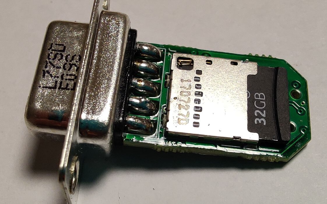
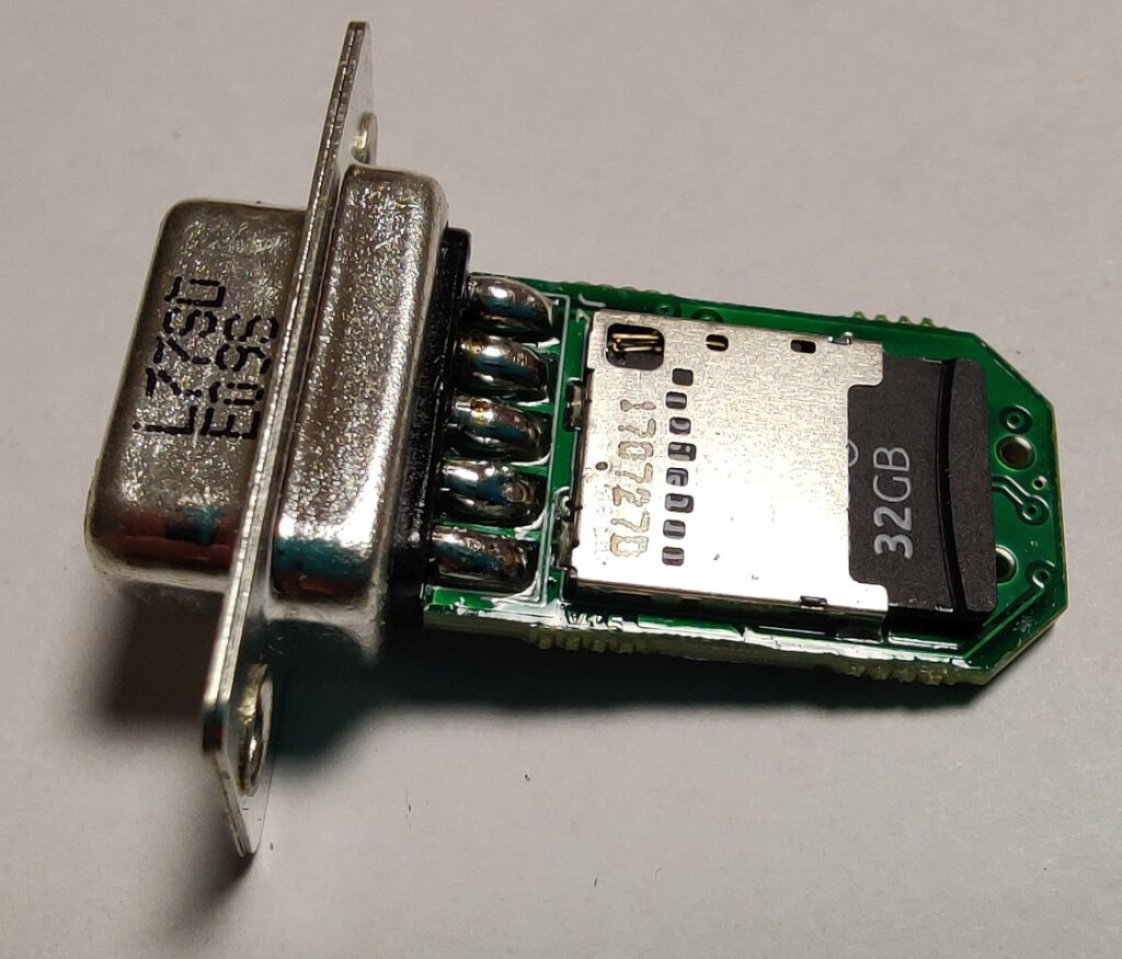
For our steering system, we needed a robust way to log the state of the electronics. If something goes wrong the customer can send data back to get assistance. In our control unit, I use a Sub-D Port to flash the board and parametrize it afterward. The MCU writes data to the serial port whether the listener is present or not. An easy way to log data is to use OpenLog [https://www.sparkfun.com/products/13712] to write the serial output to a microSD card. I actually used the OpenLog card from Sparkfun for the first prototypes and on your vehicles until I got the first batch of the new design. I decided to create the add-on dongle to the system with a secure fixture to the control box and easy access to the memory card.
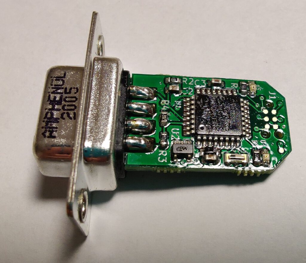
I started with an open hardware OpenLog v. 15 board and changed it. It was converted to KiCAD as I LOVE it. First of all, I added two inner Layers to get better electromagnetic characteristics and make routing a little bit easier. It adds some cost to a product, but it is not much compared to the rest of the BOM. The batches I needed were between 20 and 50 so the added cost didn’t matter that much.
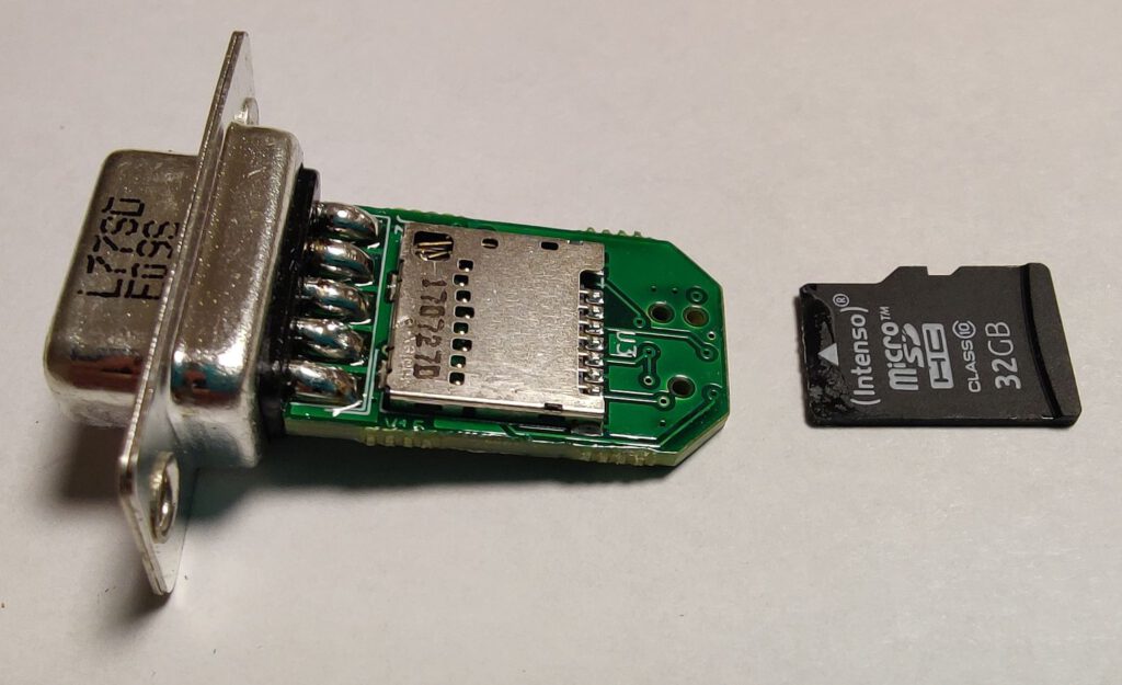
In the first try I kept SparkFun PRT-00127 microSD cardholder. I really liked the clicking sound of the retaining mechanism. But for the second batch of 50, only 30 parts were available so I had to find an alternative. In this design I use a molex part with a regular retaining mechanism. It is maybe not that safe but it gets the job done and costs nearly 2$ less pro part.
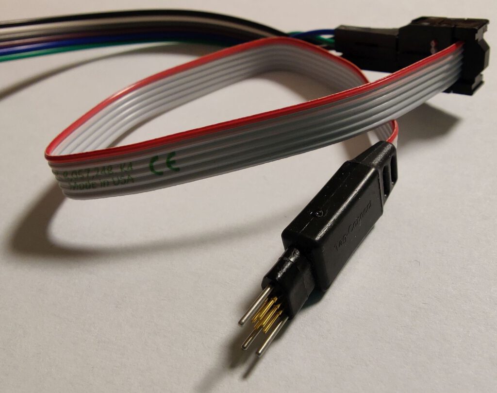
Many PCB manufacturers can get your chips flashed at the factory, but I decided to do it myself for the first couple of batches. To keep the design compact I decided to add a non-permanent connector for flashing. To use it you need 3 holes to help entering the connector as well as 6 contact pads. By the way, it also comes for free :).

You can find a compatible cable from microhip. I used TC2030-IDC-NL from Tag-Connect: https://www.tag-connect.com/product/tc2030-idc-nl
I used Arduino Nano as an ISP and connected it as follows:
- D12 MISO
- 5V VCC
- D13 SCK
- D11 MOSI
- D10 RESET
- GND GND

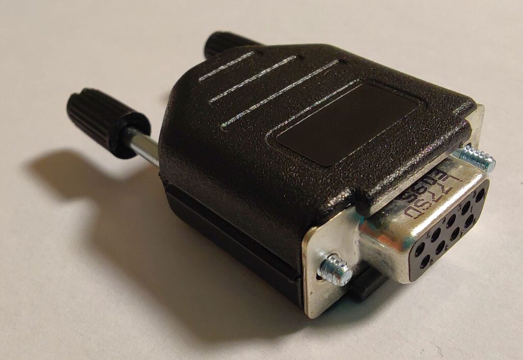
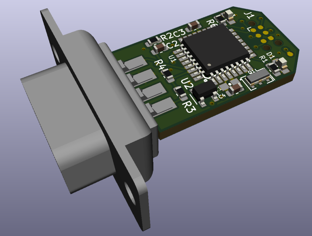
For the connection to my control unit, I took a Sub-D receptacle. Not many know (or maybe I am the only one who was baffled by it), that you can solder a PCB between the solder cups of the connector. This leads to a compact, but also robust design. You can also fix it with screws to an appropriate control unit.
The pinout in my control box is:
- NC
- NC
- NC
- NC
- TX0 (From card to the box, is not in use)
- RAW: in my case 5 V power supply
- GND
- NC
- RX0 @ 5 V signal (from box to the microSD-card)
Caution: on the first run I chose the default PCB width settings. The connector still fits but requires some force to be mounted. The manufacturer (in my case PCBway) decided not to take a risk and sent me the PCBs with no connector on as well as a box with connectors. So I had a nice evening soldering everything in place.
The fast plugging helps if you need to flash 50 devices. The whole flashing actually took me nearly an hour. I adapted the openLogger software to work with 38400 bauds of my system. For the flashing I used ArduinoISP software with a higher baud rate.
A CMD file like this was used to set the fuses and flash the chip:
"C:\Program Files (x86)\Arduino\hardware\tools\avr/bin/avrdude" -C "C:\Program Files (x86)\Arduino\hardware\tools\avr/etc/avrdude.conf" -v -patmega328p -cstk500v1 -PCOM9 -b115200 -e -Ulock:w:0x3F:m -Uefuse:w:0xFD:m -Uhfuse:w:0xDA:m -Ulfuse:w:0xFF:m
"C:\Program Files (x86)\Arduino\hardware\tools\avr/bin/avrdude" -C "C:\Program Files (x86)\Arduino\hardware\tools\avr/etc/avrdude.conf" -v -patmega328p -cstk500v1 -PCOM9 -b115200 -Uflash:w:OpenLog.ino.hex:i
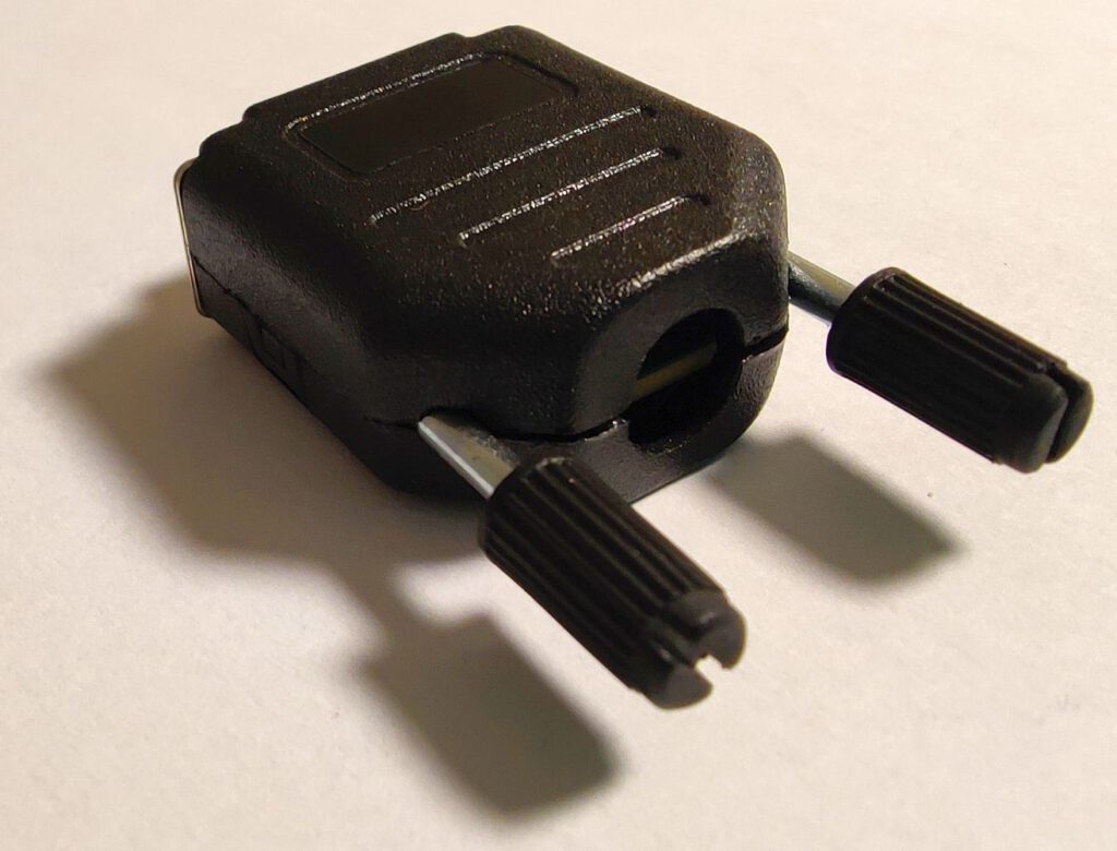
The corners of the PCB were cut to make it easier to fit in an enclosure. I wanted to 3D print an enclosure at first but as the result was not good enough at an unacceptable price I looked for a suitable sub-D backshell. I chose the biggest/cheapest here, but I guess there are a lot of similar ones. For it to fit you have to cut away some parts with a side cutter as seen in the following figure.
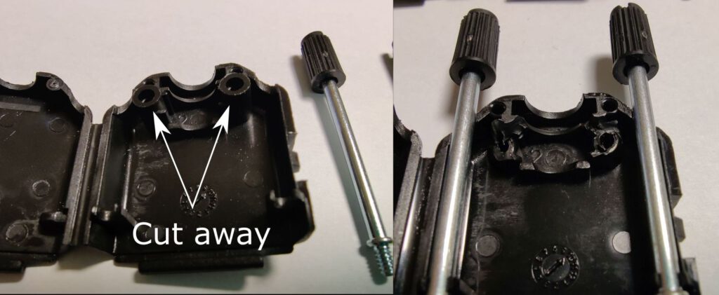
If you want you can plug the hole with a rubber plug. Furthermore, you can cover the board with silicone conformal coating to make it water-resistant. I used MG Chemicals 422C-55ML. With it you can check the quality of coverage under UV.
In the testing procedure switch on the device. On the first run, the microSD card (that should be formatted as FAT) will be initialized. On the second run the new file will be created.
With this blog I provide everything to make your black box dongles:
- Design of the PCB in KiCAD
- Bill of material
- Production data (Gerber, Holes, Positions for a pick-and-place machine)
- My versions of openlogger and Arduino ISP with changed baud rates
- https://github.com/Coolstep/OpenLogger_SubD
This device works perfectly for me but I cannot guarantee that it will work for you. Feel free to contact me if you have some ideas on how to make it better. And please don’t use it to create nuclear weapons and cat-pinching-devices.
